Siemens SISTORE AX9 User Manual
Browse online or download User Manual for Security cameras Siemens SISTORE AX9. Siemens SISTORE AX9 User`s manual
- Page / 92
- Table of contents
- TROUBLESHOOTING
- BOOKMARKS
- SISTORE AX9/AX16 (V2.5) 1
- User’s Manual 1
- Contents 3
- Preface 7
- Important Safeguards 8
- SISTORE AX9 AX16_EN.doc 10
- 1.2 Technical Overview 12
- 2 Installation 13
- 2.6 Connecting the Monitor 14
- 2.7 Connecting Audio 15
- 2.8 Connecting Alarms 15
- 2.8.2 GND (Ground) 16
- 2.8.4 ARI (Alarm Reset In) 16
- 2.8.1 AI 1 to 16 (Alarm In) 16
- 2.9 Connecting to the RS485 17
- 3.2 Turning on the Power 24
- 3.3 Initial Unit Setup 24
- 3.4 Quick Setup Screen 25
- 3.5 Normal Setup Screen 26
- 3.5.2 Date/Time Setup 29
- 3.5.3 System Check Screen 32
- 3.5.4 Storage Screen 33
- 3.6.1 Camera Setup Screen 36
- 3.6.2 Alarm In Setup Screen 37
- 3.6.3 Motion Detector 38
- 3.10 Network Setup Screen 57
- 3.10.1 LAN Setup Screen 58
- 3.10.2 Modem Setup 59
- 3.11 Password Setup Screen 62
- 3.12 Config Screen 63
- 3.12.1 Archive 64
- 4 Operation 69
- 4.2.1 Active Cameo Mode 70
- 4.2.2 PIP Mode 70
- 4.2.3 PTZ Mode 70
- 4.3 Recording Video 71
- 4.4 Recording Audio 71
- 4.5 Playing Recorded Video 72
- 4.6 Searching Video 73
- 4.6.2 Date/Time Search 74
- 4.6.3 Calendar Search 74
- 4.6.4 Event Search 75
- Appendix C — Troubleshooting 82
- Appendix G — Screens Map 87
Summary of Contents
CCTV SISTORE AX9/AX16 (V2.5) User’s Manual Fire & Security ProductsSiemens Building Technologies
Preface z Circuit Overloading Consideration should be given to connection of the equipment to supply circuit and the effect that overloading of circu
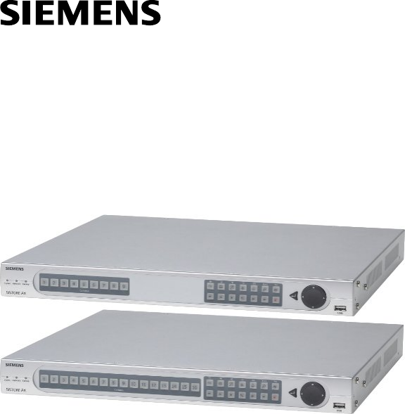
Introduction 1 Introduction 1.1 Features Your color digital video recorder (DVR) provides recording capabilities for 9 or 16 camera inputs. It provi
Introduction 1.2 Technical Overview Your DVR can replace both a time-lapse VCR and a multiplexer in a security installation. However, it has many fe
Installation 2 Installation 2.1 Package Contents The package contains the following: z Digital video recorder z Adaptor (including power cord) z A
Installation 2.4 Connecting the Video Source Fig. 4 Video input connectors. Connect the coaxial cables from the video sources to the BNC Video I
Installation 2.7 Connecting Audio NOTE: It is the user’s responsibility to determine if local laws and regulations permit recording audio.
Installation 2.8.1 AI 1 to 16 (Alarm In) You can use external devices to signal the DVR to react to events. Mechanical or electrical switches can b
Installation 2.9 Connecting to the RS485 Fig. 10 RS485 connector The DVR can be controlled remotely by an external device or control system, suc
Installation 2.11 Connecting to the UltraWide SCSI Port Fig. 12 SCSI connector A SCSI port is provided to connect external storage devices for e
Installation 2.13 Connecting to the USB Port Fig. 14 USB connector. Two USB ports are provided to connect external hard disk drives, CD-RW or fl
Liefermöglichkeiten und technische Änderungen vorbehalten. Data and design subject to change without notice. / Supply subject to availability. © 2004
Installation 2.15 Connecting the Power Cord Fig. 16 Power cord connector. Connect the DC power cord of the adaptor to the DVR, and connect the A
Configuration 3 Configuration NOTE: Your DVR should be completely installed before proceeding. Refer to Chapter 2 - Installation. 3.1 Fr
Configuration 3.1.5 Sequence Button When in the live mode, pressing the Sequence button displays another full live channel sequentially. When in one
Configuration 3.1.12 RW (Rewind) Button Pressing the RW button plays video backward at high speed. Pressing the button again toggles the playback s
Configuration 3.1.19 Enter Button The (Enter) button selects a highlighted item or completes an entry that you have made. It also sets or releases
Configuration 3.4 Quick Setup Screen Fig. 19 Quick Setup screen. The Quick Setup screen allows you to set up the most commonly used features of
Configuration 3.5 Normal Setup Screen Fig. 20 Normal Setup screen. Press the Menu button to enter the setup screen. If the Quick Setup screen ap
Configuration Fig. 22 System Information Change screen. z Highlight the box beside Unit ID and press the button. Change the number by highlight
Configuration z Use the arrow keys to highlight the first character you want in the Site Title and press the button. That character appears in the
Configuration 3.5.2 Date/Time Setup Highlight Date/Time in the Main Menu and press the button. The Date/Time setup screen appears. Fig. 26 Date/
Contents Preface...7 Compliance no
Configuration Fig. 27 Holiday Setup screen. z You can save your changes by highlighting OK and pressing the button. Selecting Cancel exits the s
Configuration z The box beside Next Synchronization displays the scheduled time for the next synchronization. If you want to synchronize the time in
Configuration 3.5.3 System Check Screen Highlight System Check in the Main menu and press the button. The System Check setup screen appears. Fi
Configuration 3.5.4 Storage Screen Highlight Storage in the Main menu and press the button. The Storage setup screen appears. The DVR displays the
Configuration CAUTION A “−“ displays when connecting a hard disk drive that was previously used for something else. In this situation, device u
Configuration 3.5.5 System Log Screen Highlight System Log in the Main menu and press the button. The System Log screen appears. Fig. 32 System
Configuration 3.6 Configuring Input Devices You can configure the video, audio and remote control devices connected to the DVR. Fig. 33 Device me
Configuration You can assign titles to each camera by highlighting the camera title box and pressing the button. A virtual keyboard allows you to en
Configuration 3.6.3 Motion Detector Fig. 37 Motion Detector setup screen. Your DVR has built-in video motion detector. Video motion detection ca
Configuration The Motion Detection Zone screen is laid over the video for the selected camera. You can set up motion detection zones by selecting or
3.2 Turning on the Power...24 3.3 Initial Unit Setup...
Configuration 3.6.4 Alarm Out Setup Screen The Alarm Out setup screen allows you to establish a schedule for each alarm output from the DVR. Fig.
Configuration 3.6.5 Audio Setup Screen Highlight Audio in the Main menu and press the button. The Audio Setup screen appears. Fig. 42 Audio Set
Configuration 3.6.6 RS232/RS485 Setup Screen The RS232/RS485 setup screen allows you to set up the RS232 and RS485 ports to communicate with externa
Configuration 3.7 Configuring Recording Settings NOTE: Pressing the REC button on the front of the DVR will cause the red LED above the but
Configuration z Highlight the box beside Field Detect. Pressing the button toggles between On and Off. When set to On, the Field Detection helps
Configuration z Highlight the box under Quality and press the button. A drop-down list appears. You can select from Very High, High, Standard and
Configuration NOTE: The Holiday (H) schedule applies to the dates you established as holidays when setting Date/Time. You can save your ch
Configuration 3.8 Event Action Setup You can program the DVR to record, activate the alarm output and/or notify the remote site whenever sensor, mot
Configuration 3.8.2 Alarm In Event Action (Alarm Out) Setup Screen The DVR can be set to react to alarm events differently by activating an internal
Configuration 3.8.3 Alarm In Event Action (Notify) Setup Screen The DVR can be set to contact a computer running RAS (Remote Administration System)
4.3 Recording Video...71 4.4 Recording Audio...
Configuration z Highlight the Sched box and press the button. A schedule screen appears. Set the schedule as described earlier. z Highlight the
Configuration 3.8.6 Motion Detector Event Action (Notify) Setup Screen The DVR can be set to contact a computer running RAS (Remote Administration S
Configuration z Highlight the Sched box and press the button. A schedule screen appears. Set the schedule as described earlier. z Highlight the
Configuration 3.8.9 Video Loss Event Action (Notify) Setup Screen The DVR can be set to contact a computer running RAS (Remote Administration System
Configuration 3.9 Display Setup Highlight the OSD, Main Monitoring or Sport Monitoring in the Main menu, and press the button to set up the on-scree
Configuration 3.9.2 Main Monitoring Setup Screen You can adjust the display dwell time for each camera displayed on the main monitor. You can also
Configuration 3.9.3 Spot Monitoring Setup Screen You can adjust the display dwell time for each camera displayed on the spot monitor. You can also
Configuration 3.10 Network Setup Screen In the Network Setup screen you can set up the DVR for LAN connections. Fig. 60 Network Setup screen. z
Configuration NOTE: The transfer speed indicates the image rate transferred to each RAS. If two remote sites (RAS) are connecting to the DVR,
Configuration The factory default LAN settings are: DHCP: Off IP Address: 192.168.1.129 Gateway: 192.168.1.254 Subnet Mask: 255.255.255.0 The
Configuration z Highlight the box beside Baud Rate of the RS232 field and press the button. A list of baud rates ranging from 300 to 115,200 appe
Configuration 3.10.4 Callback Center (Modem) Setup Screen Fig. 64 Callback Center (Modem) Setup screen. z If you have a modem connected to the
Configuration 3.11 Password Setup Screen An Administrator password is required to turn the system off, enter the setup screen, load default setups,
Configuration To lock front panel buttons, highlight Key Lock On and press the button. Once the buttons are locked, pressing any front panel button
Configuration 3.12.1 Archive The Archive screen can be used to archive video automatically or manually. Fig. 67 Archive screen. Selecting Update
Configuration You can save your changes by highlighting OK and pressing button. Selecting Cancel exits the screen without saving the changes. Sele
Configuration 3.12.2 Clip Copy The Clip Copy screen can be used to copy video clips to an external USB hard disk drive, CD-RW drive or flash drive.
Configuration button exits the screen and returns to the Clip Copy screen without saving the changes. Fig. 71 USB Device Selection screen. When th
Configuration 68 NOTE: During clip copy, you can neither change the system date and time, shut the system down, switch to the Quick Setup mode
Operation 4 Operation NOTE: This chapter assumes your DVR has been installed and configured. If it has not, please refer to Chapters 2 and
Preface Preface Compliance notice of FCC This equipment has been tested and found to comply with the limits for a CLASS A Digital Device, pursuant to
Operation 4.2.1 Active Cameo Mode You can enter the Active Cameo mode by pressing the button in any multi-view format. The grey-highlight box at
Operation Fig. 74 Preset View screen. You can save camera position settings as “presets” so that you can go directly to desired views. Once you ha
Operation 4.5 Playing Recorded Video Once video has been recorded, you can view it by pressing the Play/Pause button. When playing video for the fir
Operation 4.5.7 FF (Fast Forward) Button Pressing the FF button plays video forward at high speed. Pressing the button again toggles the playback s
Operation 4.6.2 Date/Time Search Fig. 77 Date/Time Search screen. z Move the cursor over the date and press the button. You can use the Left
Operation NOTE: The time bar is in one-hour segments. If a segment is highlighted, it means that some video was recorded during that hour.
Operation Fig. 80 Event Search (by Camera) screen. Fig. 81 Event Search (by Event) screen. Highlight the box beside Search by and press the but
77 Siemens Building Technologies SISTORE AX9 AX16_EN.docFire & Security Products 09.2004
Appendix A — USB-IDE Hard Disk Drive Preparation 5 Appendix A — USB-IDE Hard Disk Drive Preparation 5.1 Preparing the USB-IDE hard disk drive in Win
Appendix A — USB-IDE Hard Disk Drive Preparation 5.2 Preparing the USB-IDE hard disk drive in Windows 98 NOTE: Preparing a USB-IDE hard disk
Preface Important Safeguards WARNINGTO REDUCE THE RISK OF ELECTRIC SHOCK, DO NOT REMOVE COVER (OR BACK). NO USER-SERVICEABLE PARTS INSIDE. REFER
Appendix B — Reviewing Video Clips 6 Appendix B — Reviewing Video Clips NOTE: It is suggested that the computer used for the Player program h
Appendix B — Reviewing Video Clips The Current Image Information window displays information about the current image. Camera Title displays the camer
Appendix C — Troubleshooting 7 Appendix C — Troubleshooting Problem Possible Solution No Power z Check power cord connections. z Confirm that t
Appendix D — Connector Pin Outs 8 Appendix D — Connector Pin Outs 8.1 Alarm I/O Connector and RS485 Connector Pin Outs Pin Number Pin Assignmen
Appendix E — Connection Diagram 9 Appendix E — Connection Diagram 9.1 Sample I. Connecting the Dome Camera and SISTORE AX9/AX16 RS485/ Alarm I/0
Appendix E — Connection Diagram 9.3 Sample III. Connecting the SISTORE AX and SCU RS485RS232-RS485Converter RS232-Current Loop ConverterAXAX9/AX16
Appendix F — Recording Table 10 Appendix F — Recording Table 10.1 All 16 Channel Recording Times with 250 GB HDD (Days) Recording Quality (Stand
Appendix G — Screens Map 11 Appendix G — Screens Map 87 Siemens Building Technologies SISTORE AX9 AX16_EN.docFire & Security Products 0
Appendix H — Specifications 12 Appendix H — Specifications VIDEO Signal Format PAL or NTSC (selector switch) Video Input Composite: 9 or 16 loopi
Appendix H — Specifications STORAGE Primary Storage EIDE hard disk drive (up to 2) Secondary Storage SCSI hard disk drive (RAID) Backup Storage US
Preface z Servicing Do not attempt to service this equipment yourself. Refer all servicing to qualified service personnel. z Damage requiring Servi
Keyword Index 13 Keyword Index A Active Cameo Mode, 71 AI 1 to 16 (Alarm In), 16 Alarm Button, 22 Alarm I/O Connector, 85 Alarm In Event Action (Alar
Keyword Index Q Quick Setup Screen, 25 R REC (Record) Button, 23 Record Mode Setup Screen, 44 Recording Audio, 73 Recording Table, 88 Recording Video,
Issued by SGS Fire & Security Products D-76187 Karlsruhe www.sbt.siemens.com/FSP © 2004 Copyright bySiemens Building Technologies AGData and d
More documents for Security cameras Siemens SISTORE AX9


Related products and manuals for Security cameras Siemens SISTORE AX9

 (3 pages)


 (208 pages)
 (26 pages)
© 2020, manymanuals.com. All rights reserved. | 0.682 s |
 Manymanuals.com
 Manymanuals.de
 Manymanuals.fr
 Manymanuals.it
 Manymanuals.pl
 Manymanuals.cz
 Manymanuals.es
 Manymanuals-pt.com
Comments to this Manuals