Siemens IGWIPS200-1 User Manual
Browse online or download User Manual for Computer Accessories Siemens IGWIPS200-1. Siemens IGWIPS200-1 User Manual
- Page / 36
- Table of contents
- BOOKMARKS
- ) ) ) ) ) ) ) ) ) 1
- TABLE OF CONTENTS 3
- SECTION TITLE PAGE 3
- LIST OF FIGURES 3
- FIGURE AND TITLE PAGE 3
- PREFACE 4
- INTRODUCTION 6
- United States 8
- INSTALLATION 9
- IGWiPS200-1 10
- Precautions - English 11
- Précautions - Français 11
- ENVIRONMENTAL CONSIDERATIONS 11
- CAUTION 11
- USER SUPPLIED MATERIALS 13
- IGWiPS200-1 15
- IMPORTANT 16
- MOUNTING THE DIN RAIL 16
- Figure 4 Module Features 17
- May 2007 19 21
- May 2007 22
- HAZARD LABEL 30
- TRANSCEIVER RSSI 31
- SPECIFICATIONS 33
- WARRANTY 36
Summary of Contents
INSTALLATION GUIDE IGWiPS200-1 Rev 3 May 2007 ) ) ) ) ) ) ) ) ) ) ) ( ( ( ( ( ( ( ( ( ( ( (
IGWiPS200-1 DANGER Electrical shock hazard Explosion hazard Will cause death or injury. • Remove power from all wires and terminals before wo
IGWiPS200-1 Changes or modifications not expressly approved by Siemens will void the user’s authority to operate the equipment. This product is in
IGWiPS200-1 ANTENNA CONNECTORS AND SURGE VOLTAGE PROTECTION Each transceiver has an MCX female antenna connector. The base 3-1/2", 1/4-wave whip
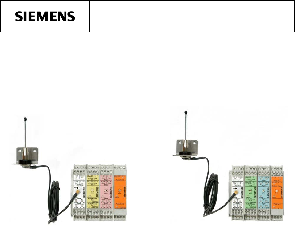
IGWiPS200-1 Control Room At the control room, there is one master transceiver and complementing I/O: one analog output module, and one digital outpu
IGWiPS200-1 A. Analog Output and Digital Output Fault Response Selections Three I/O modules (4-Channel Analog Output Module, 8-Channel Digital Output
IGWiPS200-1 Pulse Output Module (See Figure 18 on page 26) There are two DIP switches for each channel: switches 1 and 2 for channel 1, switches 3
IGWiPS200-1 MOUNTING THE DIN RAIL At each installation site, mount the DIN rail and DIN rail mount modules (e.g. transceiver, I/O modules, power suppl
IGWiPS200-1 Each module has a moveable, spring-loaded mounting lip to assist in mounting a module, sliding a module along the DIN rail, and removing
IGWiPS200-1 MOUNTING THE 1/4-WAVE WHIP ANTENNA Mount the 3-1/6" (80.4 mm) high, omnidirectional whip antenna5, shown at right, within 5' (1.
IGWiPS200-1 Electrical Connections – Power and I/O connections are completed through screw actuated compression terminals. Connector blocks can be
IGWiPS200-1 Transceiver Wiring Examples Five transceiver wiring examples are provided below. Figures 6, 7, and 8 show typical transceiver wiring for 2
IGWiPS200-1 Figure 7 Transceiver Wiring, 4-20 mA Current Loop with 3-Wire Device May 2007 19
IGWiPS200-1 Figure 8 Transceiver Wiring, 4-20 mA Current Loop with 4-Wire Device May 2007 20
IGWiPS200-1 Figure 9 Transceiver Wiring, Analog and Digital Outputs Figure 10 Transceiver Wiring, Analog Output Wiring for a Loop Powered Dev
IGWiPS200-1 Transceiver RF Link and Output State Wiring Options This section describes the transceiver RF link status relay and the analog output and
IGWiPS200-1 Green Faceplate Figure 12 4-Channel Analog Input Module Wiring Yellow Faceplate Figure 13 4-Channel Analog Output Module Wiring
IGWiPS200-1 Blue Faceplate Figure 14 8-Channel Digital Input Module Wiring Pink Faceplate Figure 15 8-Channel Digital Output Module Wiring
IGWiPS200-1 Multiple Colors Faceplate Figure 16 Combination Input and Output Module Wiring (One Analog Input, One Analog Output, Two Digital Inpu
IGWiPS200-1 Orange Faceplate Figure 17 2-Channel Pulse Input Module Wiring Orange Faceplate Figure 18 2-Channel Pulse Output Module Wiring M
IGWiPS200-1 ASSIGNING AND SETTING I/O MODULE ADDRESSES Module addresses are 1 through 8, as shown on the module faceplates in Figure 19. The top row
IGWiPS200-1 TABLE OF CONTENTS SECTION TITLE PAGE PREFACE...
IGWiPS200-1 HAZARD LABEL A label, similar to that shown here, is included in a WiPS shipment. The installer or user should post this label in an appro
IGWiPS200-1 4. Locate the Hop Key (a small circuit board) at the rear edge of the top circuit board, see the figure below. Unplug the Hop Key and s
IGWiPS200-1 0.01.02.03.04.0-115 -110-105-100-95 -90 -85-80-75Signal Strength (-dBm)+DC VoltsRSSI vs DC VoltageMG00446a Figure 21 Received Signal Str
IGWiPS200-1 PULSE OUTPUT MODULE DIAGNOSTIC LED’S There are 3 diagnostic LED’s on the pulse output module: Status LED: On solid when I/O is functio
IGWiPS200-1 Digital Input Module Channels ...8 Digital Input Voltage Range...
IGWiPS200-1 Combination Input/Output Module Channels ...1 analog input 1 analog outp
IGWiPS200-1 WARRANTY (a) Seller warrants that on the date of shipment the goods are of the kind and quality described herein and are free of non-confo
IGWiPS200-1 PREFACE CONVENTIONS AND SYMBOLS The following symbols may be used in this manual and may appear on the equipment. The reader should becom
IGWiPS200-1 • For devices with explosion protection: training, instruction or authorization to work on electrical circuits for systems that could c
IGWiPS200-1 INTRODUCTION This publication describes installation of the Siemens Wireless Process Solution (WiPS) 200 Series Two-Way Multipoint-To-Poin
IGWiPS200-1 Each transceiver and each I/O Expansion module has bus connectors on both sides of its cover: a male connector on one side, a female con
IGWiPS200-1 PRODUCT SUPPORT When contacting Siemens for support: • Please have complete product information at hand: • For hardware, this informati
IGWiPS200-1 INSTALLATION This section provides installation procedures for a WiPS 200 Series wireless network. A wireless network contains a master
Related products and manuals for Computer Accessories Siemens IGWIPS200-1
 (2 pages)
© 2020, manymanuals.com. All rights reserved. | 1.956 s |
 Manymanuals.com
 Manymanuals.de
 Manymanuals.fr
 Manymanuals.it
 Manymanuals.pl
 Manymanuals.cz
 Manymanuals.es
 Manymanuals-pt.com
Comments to this Manuals